The Scan to BIM: from the point cloud to the BIM Model

What is the “Scan to BIM”?

Scan to BIM corresponds to the process of modeling a building based on its Point cloud : the 3D footprint generated following a survey of the interior (and/or exterior) of the building using technologies of 3D Scan (lasergrammetry and/or photogrammetry). This methodology makes it possible to create or update the digital model of a building based on a footprint representative of reality with centimetric precision.
Two main types of uses are recurrent depending on the project:
- the creation of a digital model from scratch, via classical modeling based on the footprint and the coordinates of the point cloud, making it possible to deduce precise dimensions;
- The updating of a digital model, by importing the point cloud into an existing model in order to detect the differences (also called “clash”) between these two representations of the building and to make the modifications necessary for an update according to the footprint of the point cloud, the latter being accurate and up to date since it was recorded on site.
The first step: the 3D survey of the building
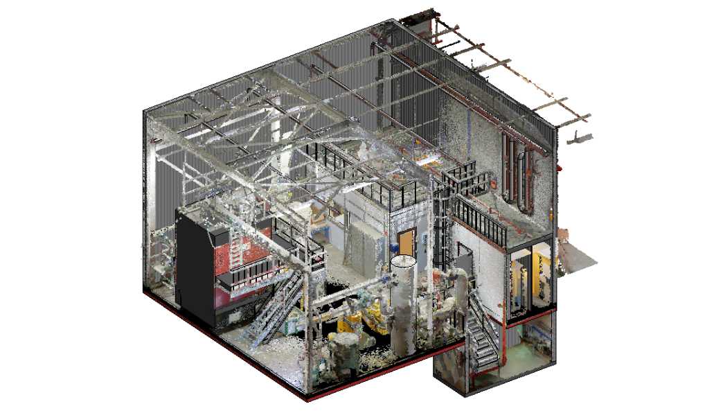
As we specify above, building surveys are operations carried out in the field by operators equipped with 3D scanners who will capture an entire building.
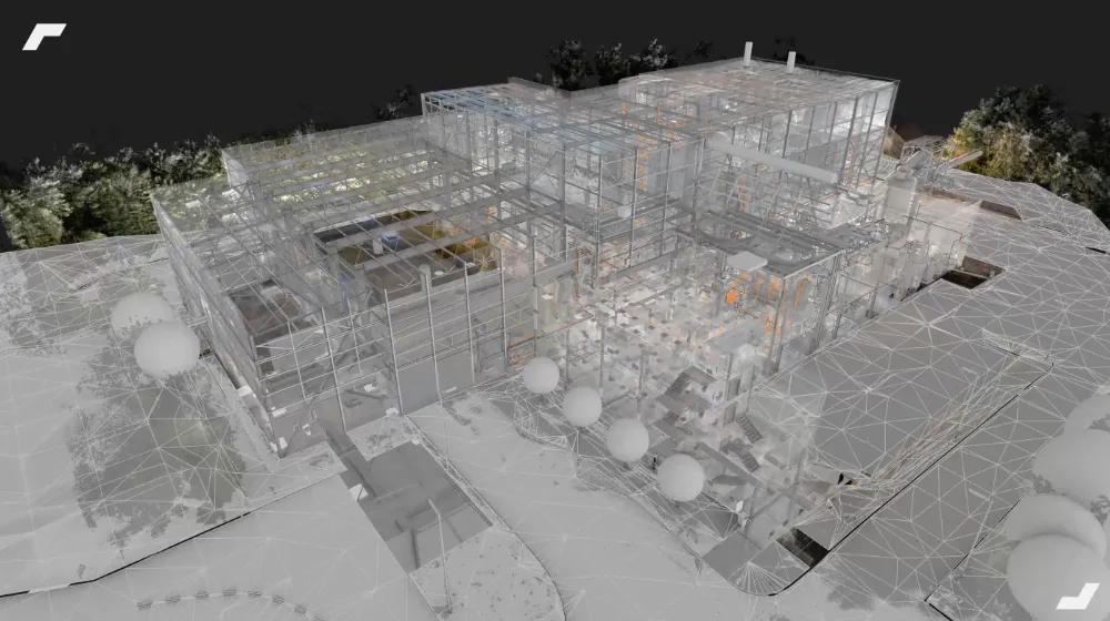
Following this 3D scan, the millions of points acquired by the scanners are then collected in the form of a point cloud, which will be delivered to the 3D modeler so that he can initiate his modeling work by importing the point cloud into his CAD software.
Initiating a modeling project based on a 3D survey will allow the modeler to benefit from an up-to-date repository of the condition of the building and common with his client, thus replacing or completing all the plans, sections, elevations and other sometimes old and erroneous documents that may be proposed to them.
Second step: post-processing scan data
Once the field data has been acquired (with the various technologies that we presented to you), it must then be loaded into a software such as Autodesk Recap Pro, Faro Scène, Leica Cyclone or other to proceed with the stage called post-processing. This is generally divided into two parts: assembling/recalibrating and then cleaning the point clouds.
The first step consists in assembling the various point clouds captured on site and in realigning them to each other. To do this, several methods can be used:
- cloud-to-cloud realignment: this involves matching clouds together according to the number of common points (coverage rate), balance (inclination) and point density;
- realignment using planes: here, the aim is to aggregate the clouds according to the number of common vertical and horizontal planes;
- realignment using targets and spheres: generally the most accurate, it uses the various targets and spheres set up in the field to adjust the clouds between them semi-automatically.
Once the clouds are assembled, it is also necessary to identify the areas that need to be cleaned (presence of mirrors, windows, people, etc.) and remove the points that correspond to these objects in the stations concerned.
Step Three: Modeling
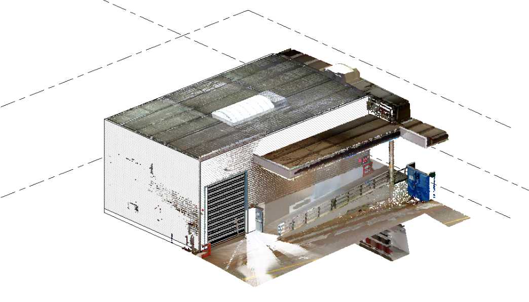
Creation of the roof
Then, it is a question of modeling the roof. Depending on the level of detail requested by the customer, the frame may or may not be represented.
Integration of MEP networks
Then, electrical, plumbing, and ventilation networks can be modeled. Again, the point cloud is used as a 3D layer and the various sections of cables, ducts or pipes are directly found in the cloud. Depending on the customer's request, the various control equipment (valves, flaps, etc.) can also be modelled.
Multi-technology capture then makes perfect sense here and we understand the advantage of having a fixed scanner in addition to a dynamic scanner if networks with diameters smaller than 1cm located at a height of more than 15m must be identified and modelled. It should be noted that depending on the type of building, other networks can be modelled such as: sprinkler, smoke extraction, compressed air, etc.
Moreover, depending on the complexity of the building, two options may arise concerning networks. The first is to model only the visible networks, the second is to identify all the networks, the scan campaign must then be much more complete (raise the false ceiling tiles, open the technical gains, raise the technical floor slabs,...) and in this case we can also model the “hidden” networks. It should be noted that even if the second option is selected, in addition to point clouds, DOE plans are often required to model all networks.
Finishing elements of the finishing work
Depending on needs, floor, wall or other coverings can also be integrated. It is then necessary to pay attention to the way in which the modeling is carried out (for example by using multi-layer walls to clearly identify the volume of each material: concrete, insulation, plasterboard and finish), this question is essential in the initial definition of modeling.
Other advantages of using a point cloud during the modeling phase
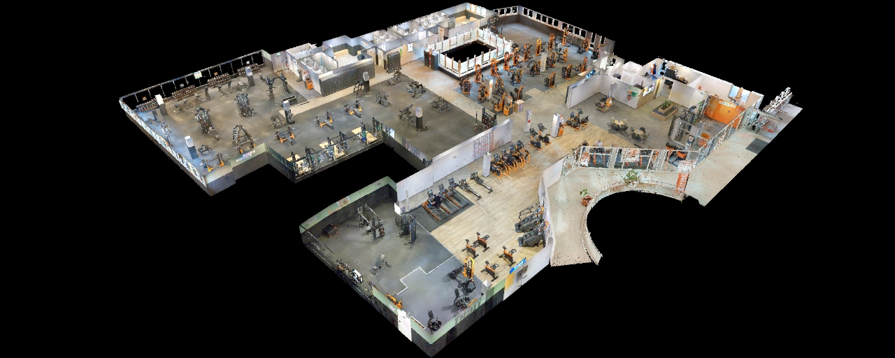
In addition to exploiting the point cloud in CAD software, the modeler can also navigate the point cloud in a 3D viewer in order to explore the building and thus inspect elements or components that may be subject to doubts, without having to travel.
At My Digital Buildings, we are also pushing this use further by offering a virtual visit. Google Street View way, accessible from the web, by assembling a set of 360° photos that our scanners systematically collect in addition to 3D data during our intervention on site. Thus, modellers benefit from a photorealistic environment to remove all their doubts during the modeling phase. In addition, this photorealistic virtual tour synchronized with the 3D and the 2D plan allows many other uses to valorize the captured data: maintenance, security, audit and diagnosis, assistance in the valuation of assets, distance training, etc.
In addition to offering direct links to photorealistic viewpoints (from the BIM model to the viewer) it is also possible to use the NavVis for Revit plugin allowing you to see the building's digital twin directly in the software.
How do new 3D scanning technologies promote Scan to BIM?
The appearance of dynamic scanners that allow large spaces to be scanned quickly, or the most recent NavVis VLX, which we use at My Digital Buildings, contribute to democratization and facilitate Scan to BIM projects.
Indeed, the possibility of capturing 3D building data more quickly has not only allowed us to reduce the costs associated with scanning operations, but also allowed us to reduce our intervention time on site, and thus the associated disruption, which can be key in the industrial sector or during an intervention on a site under construction.
On the other hand, this capacity to capture large volumes has also democratized certain uses. For example, successive surveys on sites under construction are simplified. Thus, project managers can regularly compare a building point cloud recorded on site at a certain stage of the project with the digital design model. Thus, it first of all becomes possible to implement corrective actions based on the “clashes” detected between the achievement objectives and the real one, in order to reduce the costs generated by unidentified construction errors during the construction phase. Then, this process makes it possible to update the digital model of the building throughout the project in order to move towards an “as-built” version of the model, i.e. towards a model representative of the building as built, ready to be fully exploited in a BIM work organization.
Finally, the virtual visit makes it possible to have a support accessible to everyone simply via the browser and to collaborate around a project and the spatial data of the building.
Do you have a project in mind? Discover our BIM modeling services !
To go further:
Let's study your project together
Contact us, we will study your project to provide you with an estimate as soon as possible
Contact us


To make sure you don't miss out on our news, subscribe to our newsletter now!
Receive quarterly updates directly in your inbox to stay informed about the latest news and events at My Digital Buildings.


